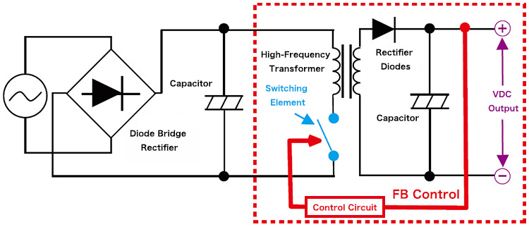
Top level diagram of the proposed control method Feedback design not Circuit Diagram control output voltage, control gain, reduce distortion,improve stability,or create instabil-ity, as in an oscillator. This short tutorial reviews feedback, with emphasis on the classic negative feedback amplifier. Notes are also included on the methods for sampling the output and injecting the control signal at the input. Feedback Principles
this control system using only core independent peripherals with some external resistors and capacitors. By combining the voltage regulation of a system with the microcontroller, the cost of the system, as well as complexity, can be reduced by eliminating the need for a dedicated controller IC. The controller also adds the ability to adjust the Let us begin our foray into the world of control systems by considering the frequency control system of Figure 2.1. Such a diagram could represent the tuning input of a voltage-controlled oscillator (VCO), laser, or motor (in which case we'd think of frequency as rotation rate or speed). The system to be controlled is often called the plant.
PDF Feedback Fundamentals: Basic Concepts and Circuit Topologies Circuit Diagram
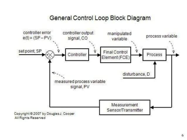
This example shows how to model a feedback control system using Simulink® signals that carry matrix and vector representations of different components of the feedback system. In this example, the controller is designed for a buck-boost converter to track a reference voltage signal. Buck-boost converters are extensively used in distributed The symbol used to represent a summing point in closed-loop systems block-diagram is that of a circle with two crossed lines as shown. The summing point can either add signals together in which a Plus ( + ) symbol is used showing the device to be a "summer" (used for positive feedback), or it can subtract signals from each other in which case a Minus ( − ) symbol is used showing that the
Design of State Variable Feedback Systems This chapter deals with the design of controllers utilizing state feedback. We will consider three major subjects: Controllability and observability and then the procedure for determining an optimal control system. Ackermann's formula can be used to determine the state variable feedback gain matrix to
PDF 8. Feedback Control Systems Circuit Diagram
6 Practical Feedback Loop Analysis for Voltage-Mode Boost Converter . Figure 5. Effect of Input Voltage Variation on the Control Characteristicof the Boost Converter More equations are created when the boost converter operates in discontinuous-conduction mode (DCM). When this happens, the double pole of the LC filter is heavily damped, and the