Time Control of a Stepper Motor with an ARM Microcontroller A Circuit Diagram Stepper motors use specialized control methods to achieve better precision than standard variable speed motors, while avoiding the expense and complexity of servo systems. For industrial automation, the term motion control usually means using an electric motor to positively drive the position, velocity, and acceleration of a physical system. A stepper motor is a type of brushless DC motor designed to divide a full rotation into a big number of precise steps. Unlike typical motors, which rotate repeatedly, stepper motors move in discrete steps, allowing for highly accurate positioning and control. Learn about how to control stepper motors, matching your stepper motor to a stepper drive and other key considerations for stepper motor design.

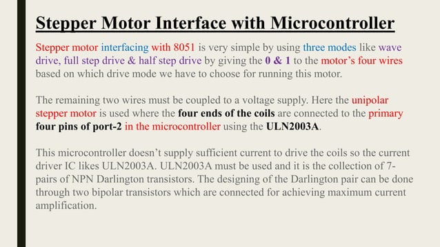
Abstract Stepper motors are vital in precision applications where there is a need for smooth movement and high resolution positioning. Recognizing the differences between fullstepping, halfstepping, and microstepping control is essential for meeting these requirements. This article closes the knowledge gap by summarizing the basics of microstepping. Introduction Stepper motors are widely used A stepper motor requires a number of step pulses to get to your desired position. Also, stepper motor coils are always energized, greatly increasing the holding torque, but turning it forcibly is difficult. The use of robotics necessitates accuracy, and, as such, stepper motors are vital in ensuring motion control precision and accuracy. These motors are critical in applications that require precise movement control without variation.
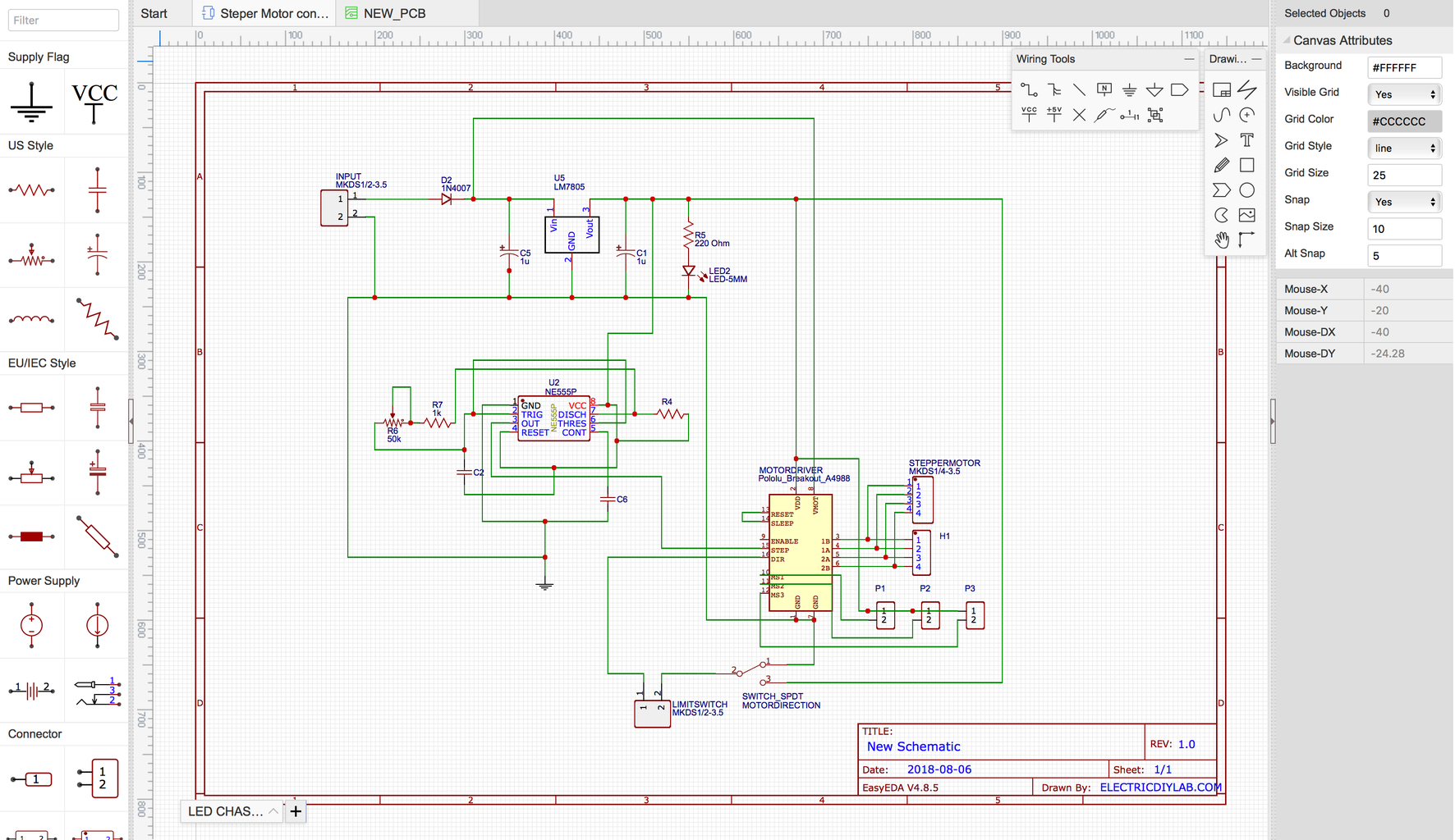
Mastering Precision: Understanding Microstepping in Motion Control ... Circuit Diagram
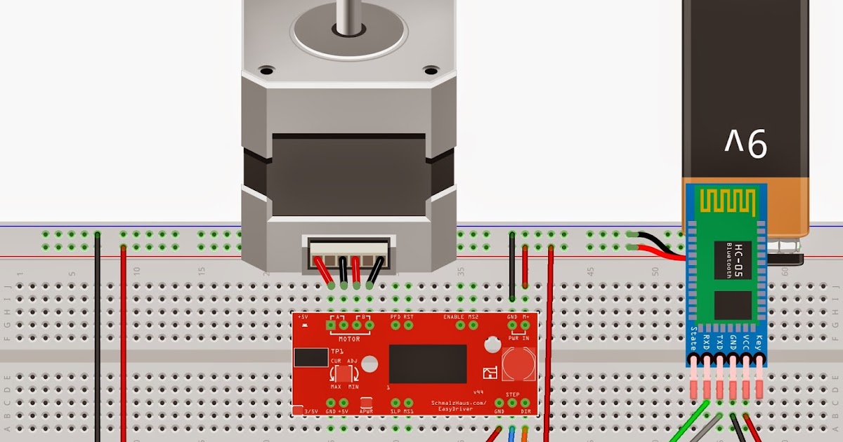
In contrast, stepper motors with position closed-loop control detect the rotor position signal and feed it back to the control unit. The system considers a step completed only after receiving the corresponding actual position response and then issues the command for the next winding phase of the stepper motor to step. Stepper Motor Control Controlling a stepper motor requires a command signal usually generated by a microcontroller or stepper controller, a power signal which is created by the drive, and a motor.
Learn how to use stepper motors with Arduino for precise motion control. Explore wiring, drivers, libraries, and where to buy at ThinkRobotics.