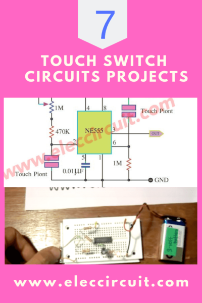
A Simple Line Following Robot Without Microcontroller Make Robots In Circuit Diagram In this third design we discus a simple IC 555 based proximity detector circuit which can be used for detecting human trespassing from a distance. Circuit Operation. An infrared proximity detector can be considered as one of the most valuable and widely used circuits in electronic automation application range.
Testing the Circuit. Point your IR remote control at the TSOP312 receiver module. Press any button on the remote control. You should see the relay click and its onboard LED will turn ON. Press the button again. The relay should click again, and the LED will turn OFF. Note that this circuit can be a bit sensitive to noise from other IR sources. Learn- How to make LM358 based IR Proximity Sensor at home. This sensor Can work as a Touchless Door Bell.Project file on the free design tool: https://easye

Remote Controlled On Circuit Diagram
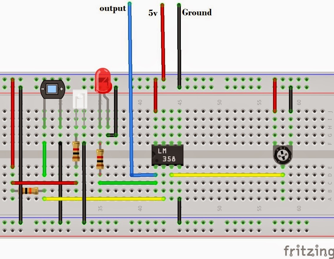
Pdf Design And Construction Of An Automatic Triggered Bell Ringer Circuit. Ir Proximity Sensor Library For Proteus The Engineering Projects. How To Make Irsensorproject Ir Sensor Detailed Working Touchless Door Bell Module At Home Diy Irproximity Robotshapers Best Science Engineering Teachnical Blogs In this video, I have made an IR Infrared sensor module using LM358 on a breadboard. I have also shared the IR sensor circuit diagram link in the description An infrared sensor is an electronic device, that emits in order to sense some aspects of the surroundings. An IR sensor can measure the heat of an object as well as detects the motion.These types of sensors measures only infrared radiation, rather than emitting it that is called as a passive IR sensor.

Tapendra Mandal Ir Proximity Sensor Circuit Diagram Touchless Door Bell Required Components 1 Lm358 Ic 2 Zero Pcb Board 3 Transmitter Receiver Pair 4 Buzzer 5 Led 6 10k. Ir Sensor Circuit Diagram Types Working With Applications. Ir Sensor Circuit Diagram Types Working With Applications. Automatic Doorbell By Using Proximity Sensor
Ir Proximity Sensor Circuit Diagram Pdf
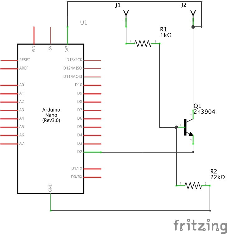
Building The Circuit Board. First, I made a prototype on a breadboard. I had to experiment a bit with R2 to find a good value. Once I had a value that worked with my phototransistor, I used Circuit Canvas to plan out how to connect the everything to a stripboard: The IR LED, phototransistor, two resistors, and nMOS transistor.. With that outline, I had a good idea of how to connect everything.